The PIONEER MAGNETICS+ PM3398B-6-1-3-E is a high-performance power module designed for use in a variety of applications.
Its high efficiency, low noise and excellent thermal performance make it ideal for demanding applications.
● Input voltage: 36V to 75V
● Output voltage: 1.2V to 12V
● Output current: 6A
Efficiency: 92%
● Operating temperature: -40°C to +85°C
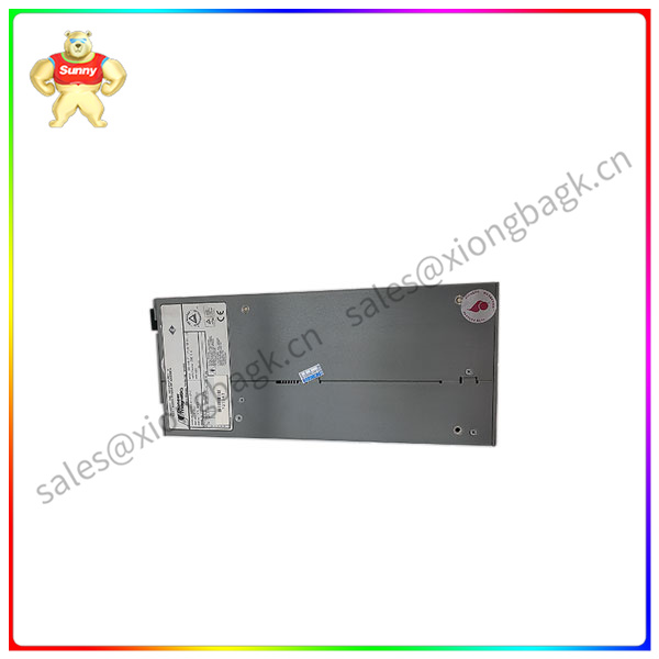
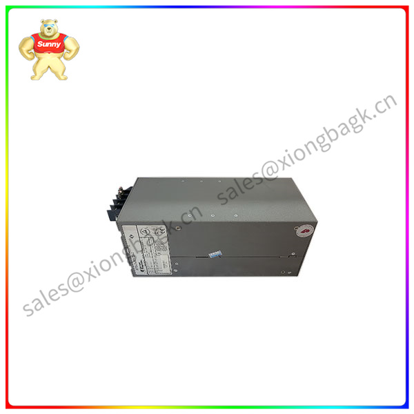
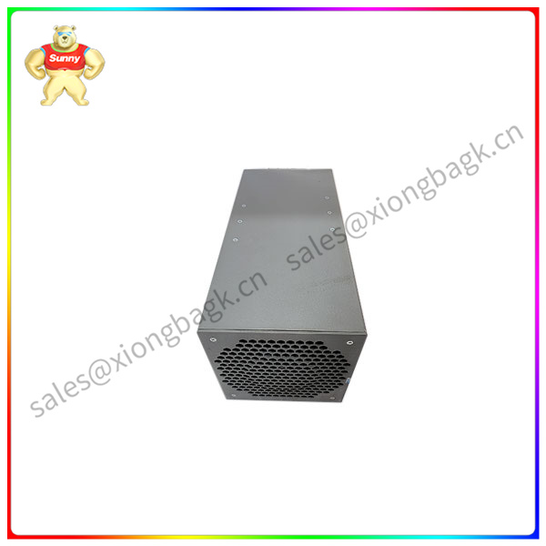
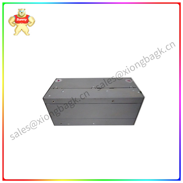
Product Details: PM3398B-6P-1-3P-E 80026-172-23 PIONEER
MAGNETICS Digital input module
What is the difference between plc digital and analog input modules? Generally speaking, we divide the analog module into three types: one is the analog input module, the other is the analog output module, and the third is the analog input /
The output module. What is the difference between a digital input module and an analog input module?
-: PLC analog input module (analog input module), also known as A/D module, converts the continuous analog signal generated by the sensor detection in the field into a digital quantity that the PLC CPU can receive
Most are 12-bit binary numbers, and the more bits of the module, the higher the resolution.
Two: PLC analog output module. The analog output module is also known as D/A module, which converts the digital quantity sent by the PLC CPU to the analog output module into the analog quantity that the external device can receive (voltage or
Electric current). The digital signal received by the analog output module is generally a 12-bit binary number, and the more digital bits of the module, the higher the resolution. The digital quantity module is to detect the external switching quantity output
Incoming state.
plc data acquisition gateway
Three: The digital input and output signal is the switching signal, or 1, the analog signal, there are two kinds, pressure or current signals, generally the signal transmitted by the transmitter, such as the force transformer detection
Water pipe pressure excitation, it will output an analog signal 4-20ma or 0-10V signal to the PLC, PLC for data processing, which is the difference between the digital input module and the analog input module.
During the input sampling phase, the PLC reads all input states and data in sequence by scanning and stores them in the corresponding cell in the /O image area. After the input sampling is complete, transfer to the user program execution
Row and output refresh phase. In both phases, even if the input state and data change, the state and data of the corresponding element in the I/O map area do not change. So if the input is a pulse message
The width of the pulse signal must be greater than one scan cycle to ensure that the input can be read in any case.


